Electrical Design
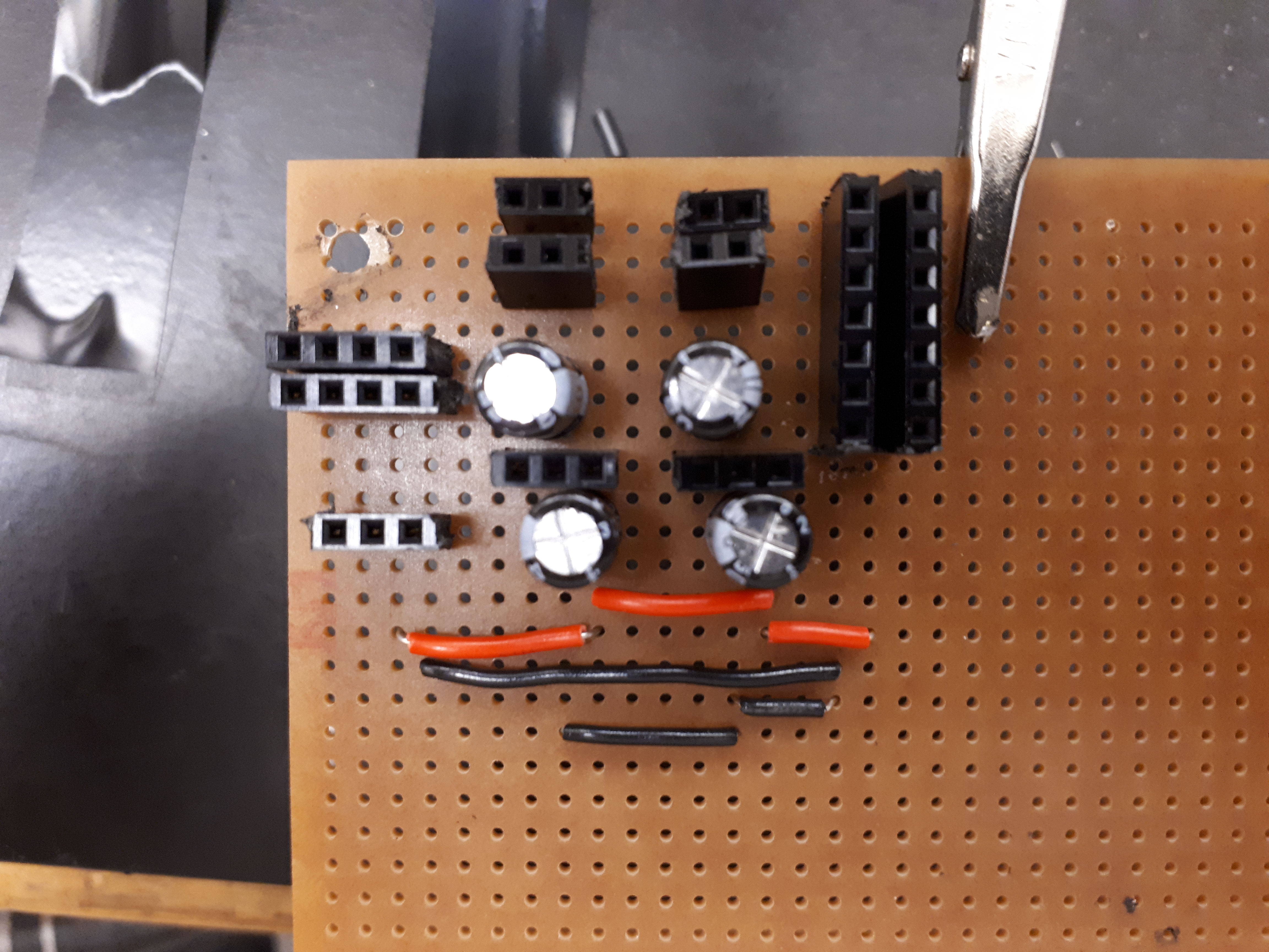
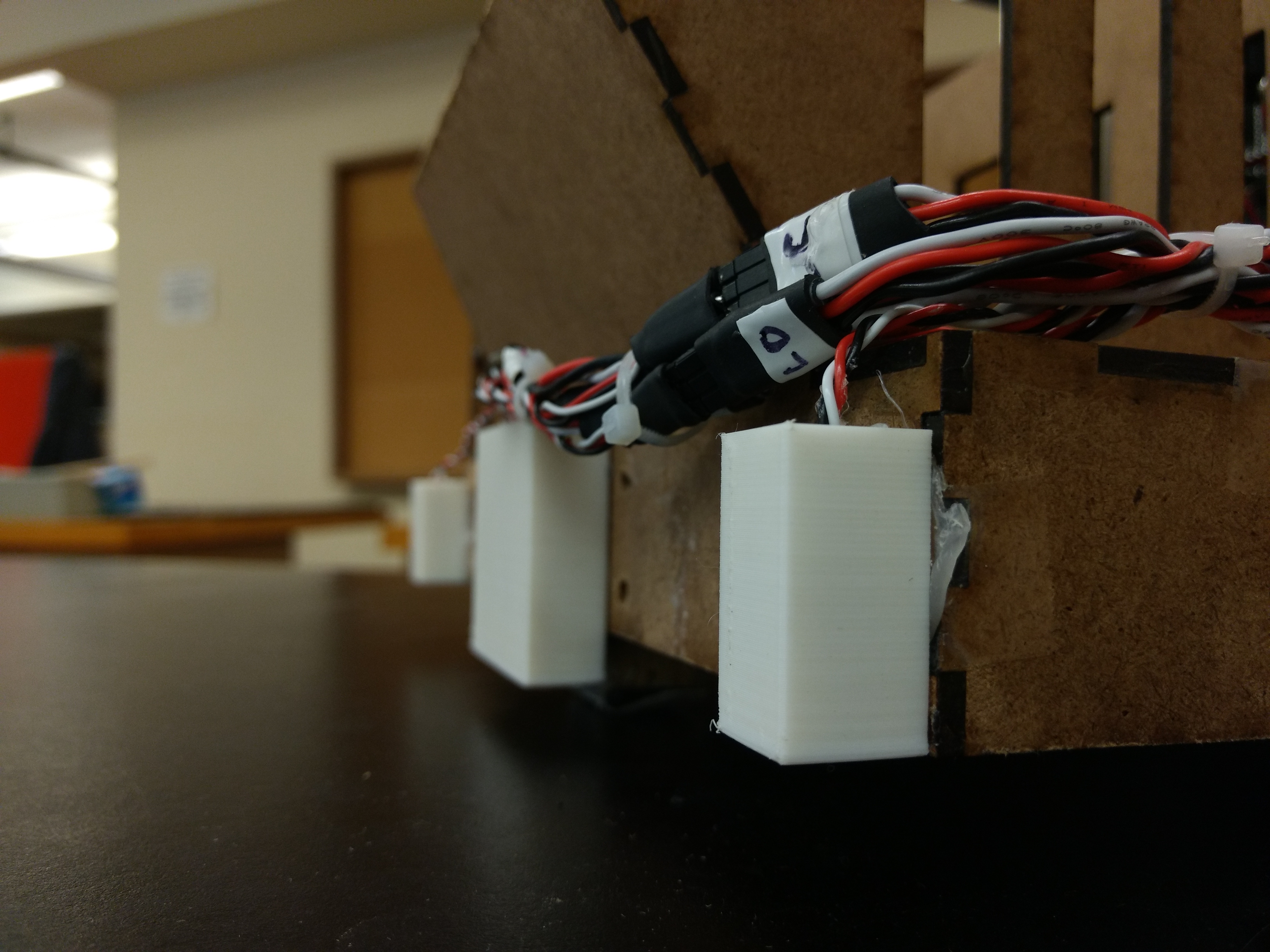
We designed the electrical system to be as simple to troubleshoot as possible. Nearly all major PCB’s were placed at the back of the robot facing outward in an easily accessible position with all transistors, voltage regulators, and cabling connections installed on female connectors which were soldered to the PCB.
TINAH
The robot uses a microcontroller system called the TINAH (This Is Not Arduino Hardware), which connects to an open-source IO board that is similar to an Arduino board. The TINAH is equipped with four DC motor outputs, three servo motor outputs, and several digital and analog IO pins.
Power Supply
The robot is powered by one three Lithium Polymer battery packs. One 14.8 V battery powers most of the electrical components on the robot and two 7.4 V batteries are connected in series to supply -14.8 V when needed. These batteries connect directly to a PCB which acts as the power supply for the entire robot. The PCB also has two sources of regulated 5 V from the 14.8 V battery which is used for servo motor power and comparator reference voltage.
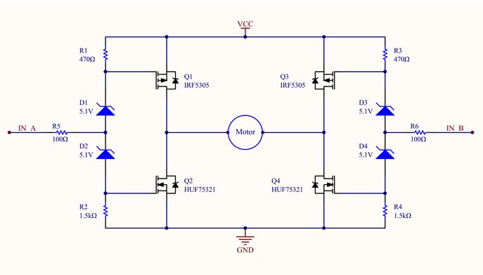
H-Bridges
The H-Bridge circuit allows the TINAH board to control a large current at 15V through to motors via it’s 5V pulse width modulation outputs. There is one H-Bridge circuit for each of the four motor outputs on the robot. The circuit is powered directly from the 14.8 V LiPo battery (VCC) and the two inputs (“IN A” and “IN B”) are run from the motor outputs of the TINAH board.
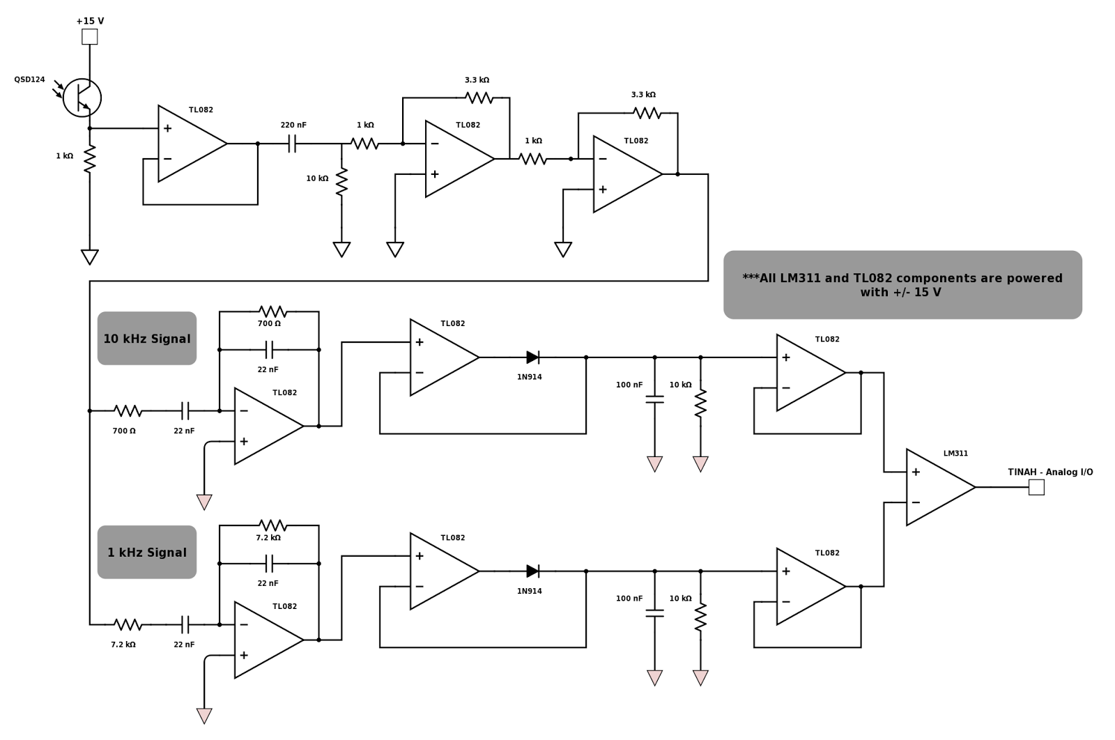
IR Filter
The robot is equipped with an IR detection system which, after amplifying the incoming signal, utilizes two sets of bandpass filters and peak detection circuits to read 1 and 10 kHz IR signals. The two outputs are then run to a comparator which outputs a digital signal that the robot can interpret in order to distinguish between the 1 kHz and 10 kHz and respond appropriately.
Sensors
Our robot employed thirteen sensors to deliver critical information about the status of the robot and it’s location on the course.
Reflectivity Sensors - These sensors are used in various locations around the robot for the purposes of line-following and crane movement feedback. Two central sensors serve as the robot’s primary means of following the line on the obstacle course. Two more sensors are installed on either side of those which give the robot the ability to detect the agent retrieval points. Two sensors are installed on each of the front corners to allow for proper navigation of sharp turns and extra detection in difficult areas of the course. Two more sensors are installed on the trolley, which give feedback of the location of the trolley and claw block. White and black tape is installed along the boom as well as at the back of the claw block which allow the sensors to pick up specific horizontal and vertical locations of the crane.
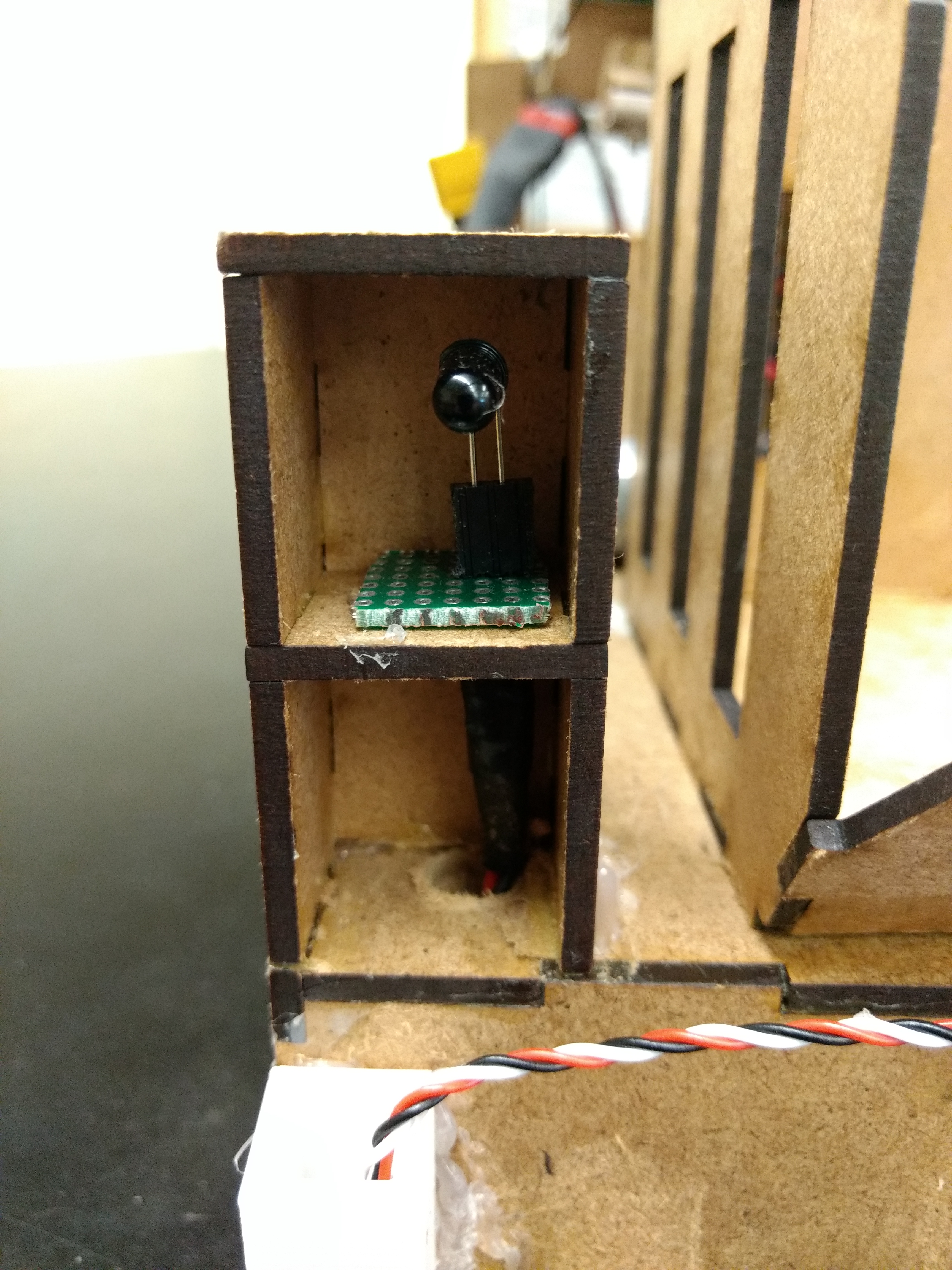
Infrared Detection Sensors - Our robot employed an infrared detection sensor, coupled with an IR filtering circuit (see IR Filtering) to detect changes in the status of the alarmed gateway.
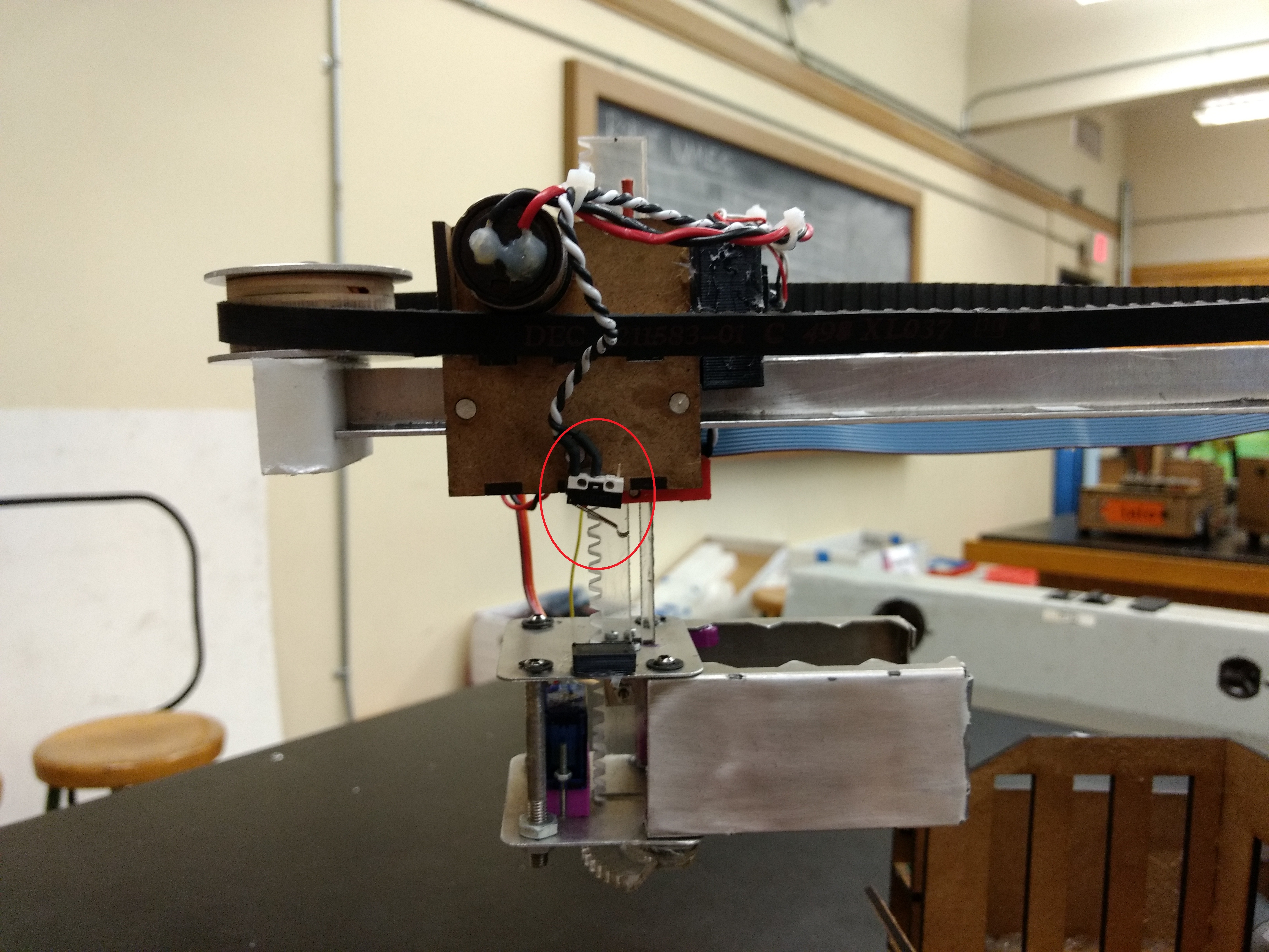
Limit Switches - Four limit switches are installed on the robot to provide feedback for certain processes. One switch is used at the trolley, claw block, and the lift to limit their movement past a practical point. They are installed such that maximum movement in a given direction is detected and motor operation can be disabled. A final switch is installed behind the lift mechanism. It is placed in such a way as to activate once the robot reaches the zipline with the lift fully extended.