Spectre
Mechanical
Chassis
Under construction
Lift
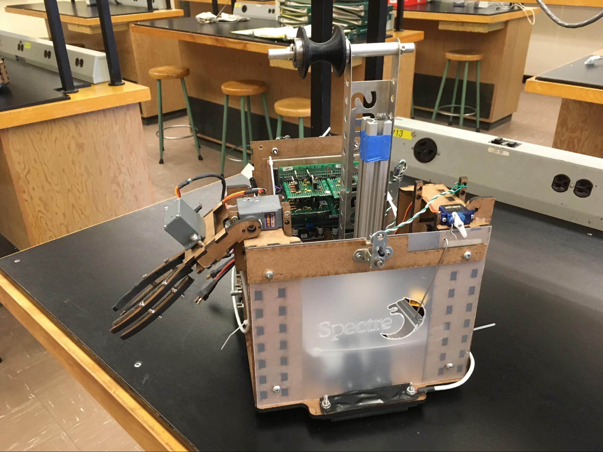
Spectre uses a lift mechanism that hoists the entire robot onto the zipline. Given the comparatively high weight of the robot, this design choice had some unique challenges associated with it.
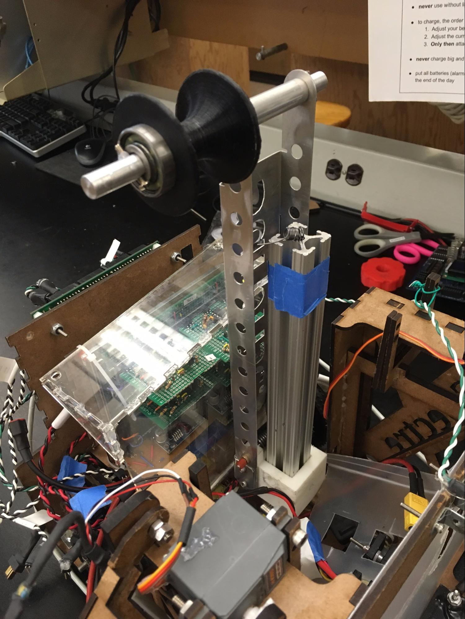
Due to height constraints, the lift mechanism is stowed for the first portion of the obstacle course. A hook-like “pin” keeps the mechanism folded over in this position. When unstowing, a MicroServo pulls out the pin and allows the lift to extend itself to its full height via a spring mechanism.
A linear rail is connected to the base of the chassis, through which a braid of Kevlar string is threaded. The Kevlar is connected to a geared motor, which winches the robot up as it turns.
After extending the lift mechanism, the robot lifts itself onto the zipline and slides down across the obstacle course.
Robotic Arm
Spectre features two identical robotic arms to retrieve toy pets and deposit them in the robot’s collection bay. As seen below, for each arm, one axis allows the arm to pivot outward and inward, and another allows the arm to grip toys. Each axis is controlled by an HK15138 servo, which outputs a maximum of 42 N-cm of torque.
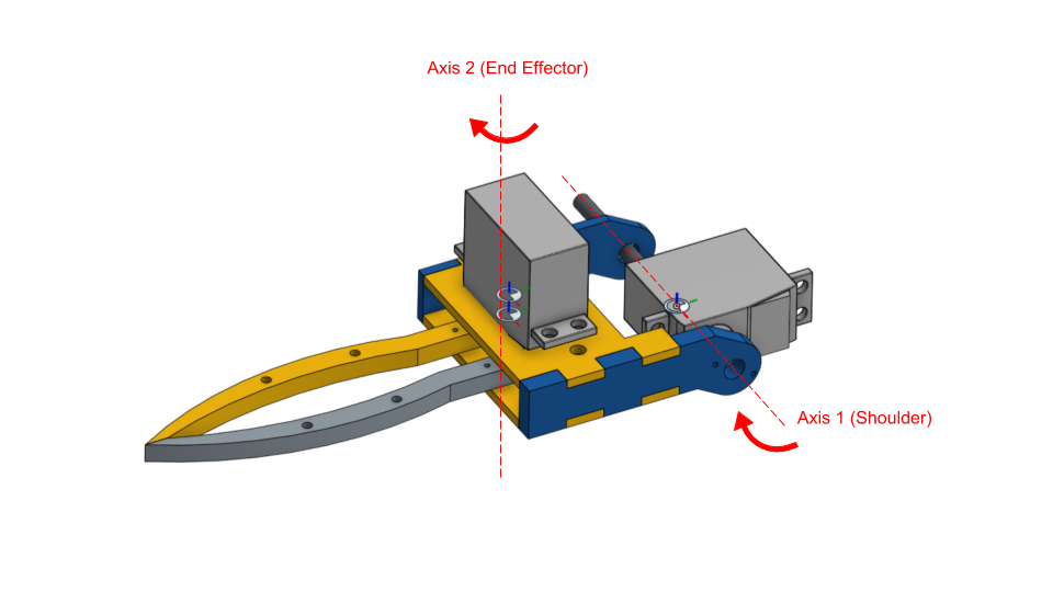
Arm Assembly (Onshape Model) with degrees of freedom shown. Full Onshape Model here
The arm is fabricated out of laser-cut MDF. We chose to use MDF because it can be easily modified to accommodate design changes without refabricating entire parts. Although acrylic and steel are stronger materials, MDF is sufficiently strong for picking up toy pets without warping or breaking.
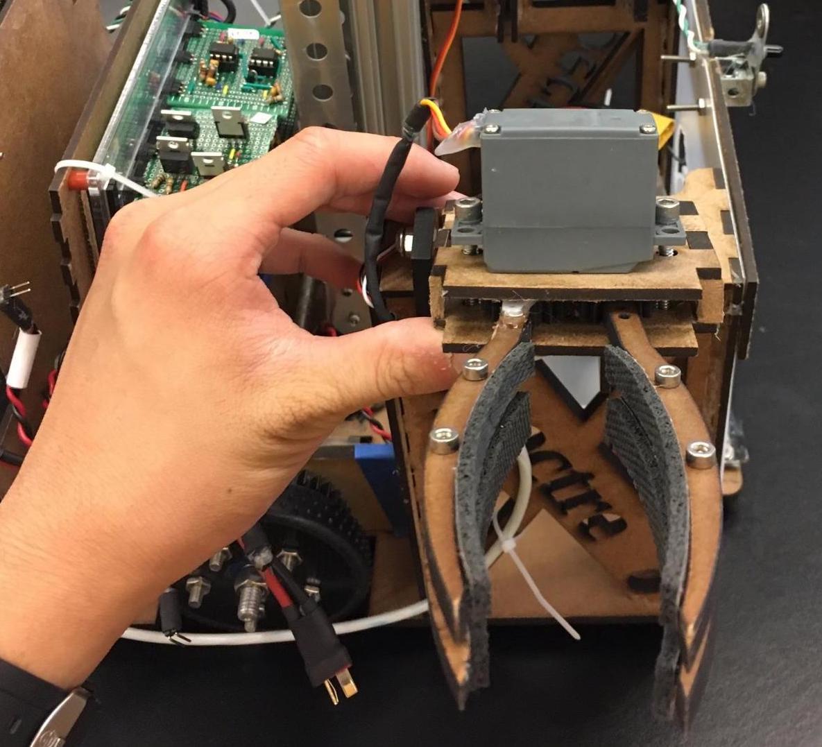
The end effector has two features that improve its ability to pick up pets. The most notable is the use of two claw pairs instead of just one. With the second claw pair, the robot is able to pick many more toys because it is able to grab toys across a wider range of heights. Once picked up, the toys are also more secure as a result of the additional claw pair; they are less likely to fall out. The second feature is the use of rubber pads to increase friction on the claw as the toys are grabbed. They are less likely to slip out of the claw as a result.
Electrical
Central Panel: Bex
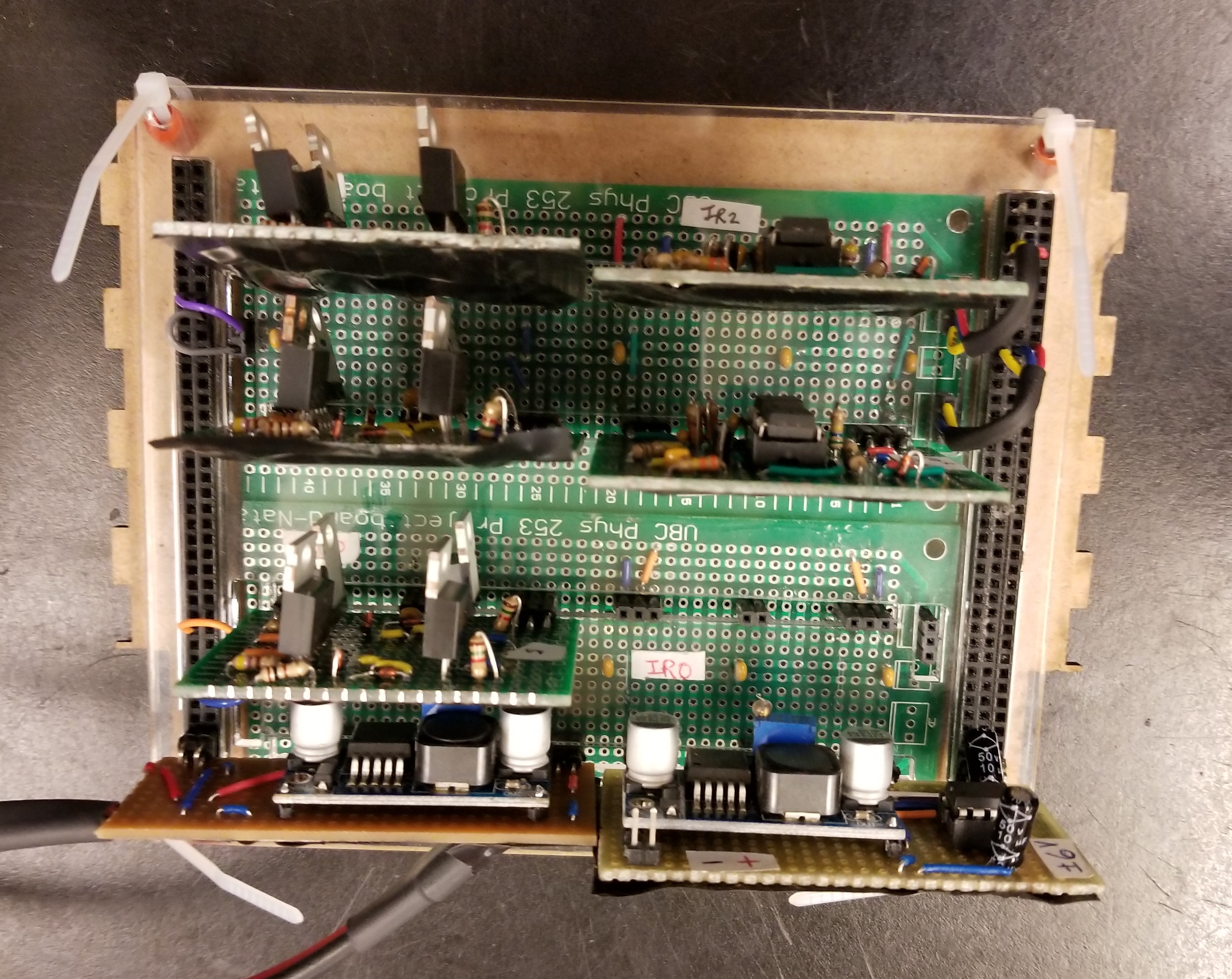
Bex is designed to be an interface between the TINAH processor and all circuits. It is a hub that allows IR, H-Bridge and power regulator circuits to be plugged in on one side, and motor and TINAH connections on the other. Bex is composed of two power rails on each side, with H-Bridges accessing the 16V power rail and the IR circuits using the +/- 6V rail. Voltage regulators for each rail sit directly below the circuits. Overall, Bex has minimized external connectors while making circuits modular and easily accessible.
H-Bridges
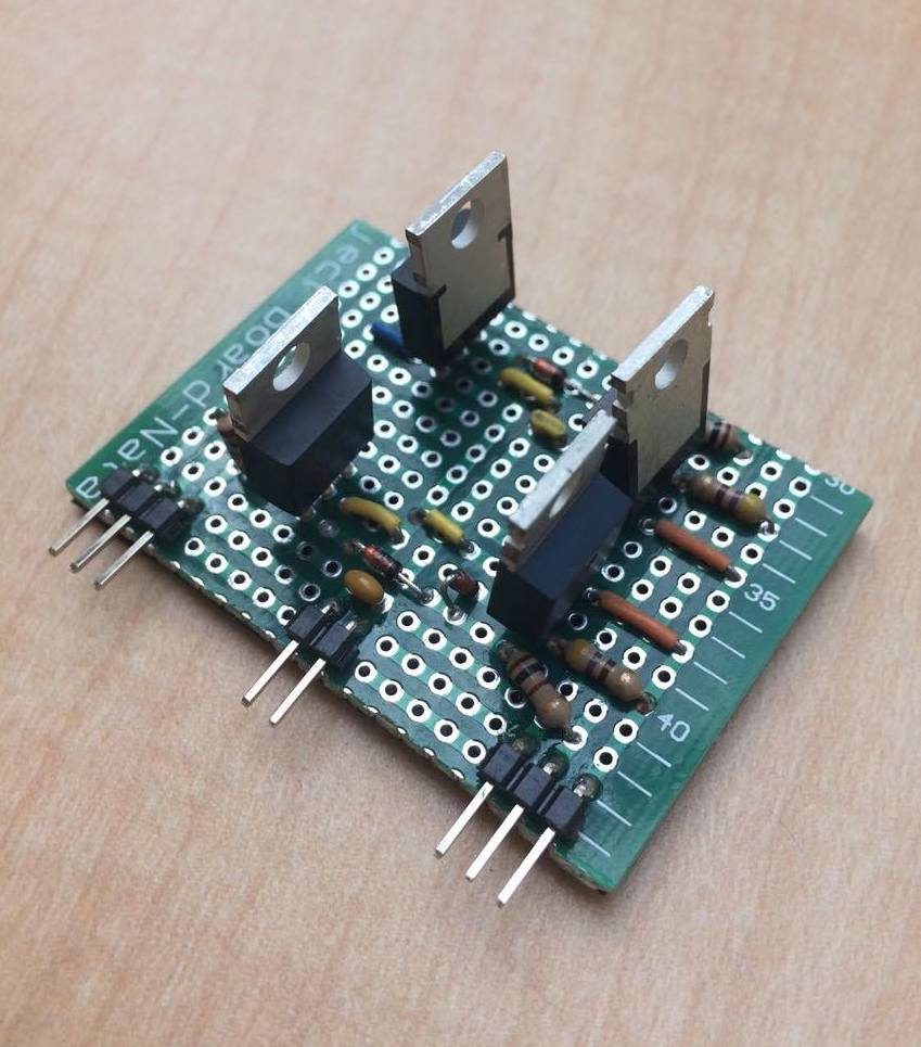
Spectre uses three H-Bridge circuits. The TINAH supplies a limited amount of current, which prompted external motor power circuitry to be made. Two H-Bridges are used for the drive train, one for each wheel. The third is used for winching the robot down the zipline.

IR Sensors
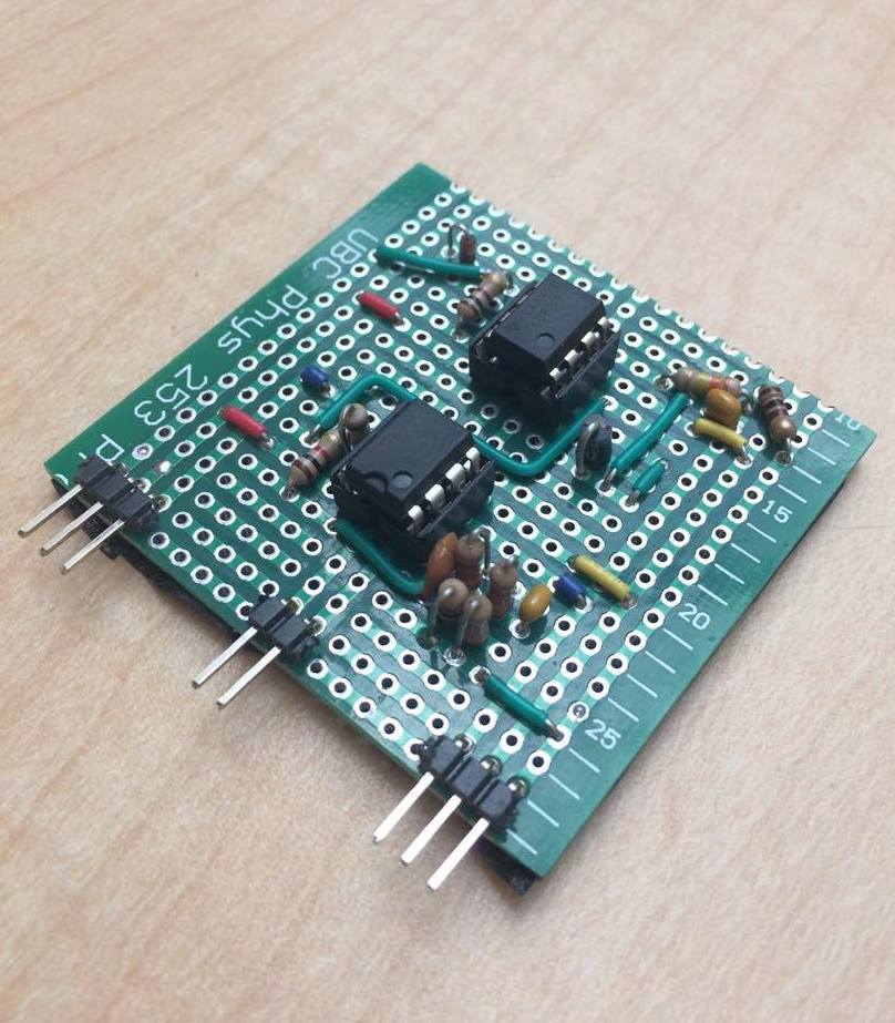
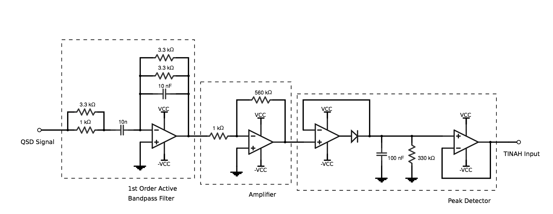
Spectre uses QSD sensors to detect the infrared signals at the gate and the zipline. Circuitry was simplified down to a sequence of first-order active bandpass filter, amplifier, and a peak follower to convert analog to DC voltage.
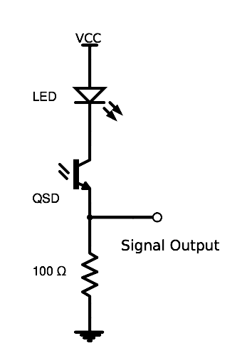
Circuits for 10kHz and 1kHz detection are separated to conserve space. This allows us to use different QSD sensors for testing. A QSD design, shown below uses the switching properties of the transistor to change the intensity of the light emitted from the LED. This design was used to help us determine the optimal location to place the QSD on Spectre, since the intensity of the LED would vary based on the viewing angle of the QSD.
Software
View Spectre’s code here.
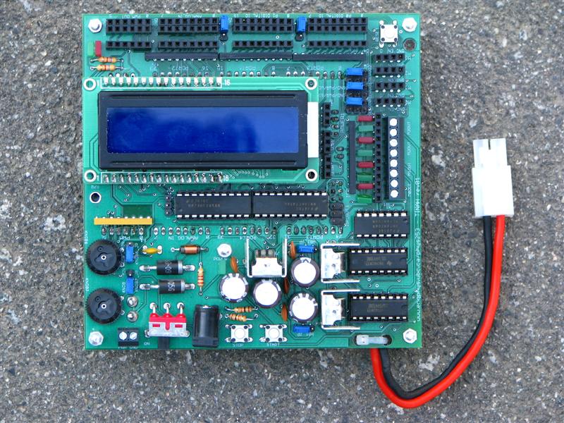
TINAH
Spectre is controlled by TINAH, an Arduino based controller inspired by the Handyboard. All of the code is written in C++ using the Arduino IDE.
Control
The software is divided into 3 states: path following, rescue and zipline. During the path following stage, the robot uses PID controls to follow tape and checks for whether or not it is safe to pass the gate. During the rescue sequence, the robot follows tape until an intersection is detected and runs the arm motors to pick up an agent. After the robot attempts to pick up all six agents, it runs the zipline sequence where it finds the zipline by dead reckoning, aligns itself and lifts itself up.
Encoders
We added wheel encoders to our robot to find the location of the gate as well as to tune the robot to turn accurately. Although the encoders’ signals had noise, we found that they worked reasonably well for short distances.